Dual LED Signal Head – Outline Specification
J Freeman - January 2026
The signal head features two multi-colour light units, each containing eight high reliability, high brightness multi-colour LEDs manufactured by Cree or Osram. These are in volume production.
The LEDs are driven by purpose designed, current regulated, variable intensity LED driver integrated circuits. This ensures high reliability, the light intensity remaining as intended over wide supply voltage and temperature ranges. This is important in reducing constraints on site wiring and power supplies.
An ambient light sensor is included. This allows LED light intensity to be varied to maximise viewing comfort under most weather conditions, including bright sunlight.
The LED drivers are controlled using a low-cost ‘ARM Cortex’ microcontroller (STM32L431CB) which features a CAN bus interface. The signal head is controlled by commands addressed to it over the CAN bus. Each signal head has a unique ID, this means that any practical number of signal heads can be ‘daisy-chained’ and controlled over the same CAN bus. This greatly simplifies site wiring.
As to be supplied, the signal head will be programmable to display any one of three aspects : -
The power-on default is to ‘Danger’.
Designed as part of a system in which safety matters, or ought to matter, switching into states other than ‘Danger’ require the appropriate command to be continuously re-sent at intervals no longer than five seconds. Failure to meet this timing constraint will cause reversion to ‘Danger’.
In addition, the microcontroller constantly monitors and decodes all CAN bus traffic. This is useful in confirming wider system integrity – should some other device crash, hog bus bandwidth or broadcast nonsense, all signal heads revert to ‘Danger’.
Use is made of ‘surface mount’ technology requiring assembly by a manufacturer suitably equipped. Professional assembly ensures excellence in build quality and high reliability.
The design uses only conservatively rated components from known, reputable and trusted manufacturers. Components are only procured through franchised industrial distributors. These minimum standards are prerequisite for production of electronic products that work to spec, with high reliability.
Data for all major components is available on the signalling web page. This is a professional design to standards for continuous use in industrial applications, and as such would be expected to exhibit MTBF in terms of years.

Design of two LED Signal Heads has been completed - single and dual lamp models.
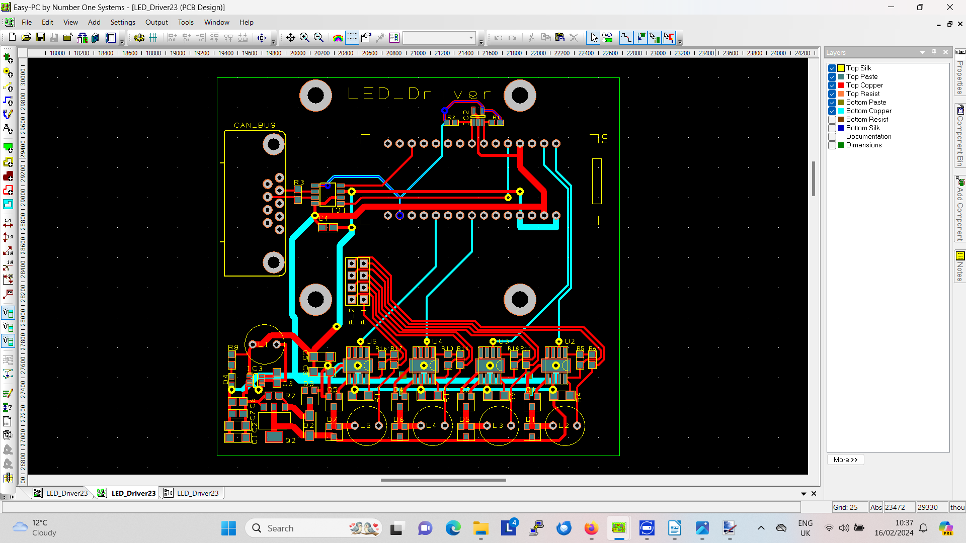
The dual lamp version builds upon the technology used in the single. Both versions use a low cost STM32L431CB ARM Cortex microcontroller to provide up to 8 independent PWM (pulse width modulator) channels used to set light intensity for up to 8 LED circuits. Schematic (here.)
A sensor of ambient lighting has been included. This is used to modulate signal brightness for enhanced driver comfort.
Future single lamp units will be part-built dual units to minimise inventory.
Printed circuit files (here), code files all to be found in the code section.
The signal head is built into a polycarbonate enclosure to IP67 spec - (see here)
There it all is. Printed circuit design files, controller firmware, enclosure, dimensions, everything there is to know about it.
End of April 2025 update.
Being much lower cost and easier to make than semaphores, LED light signals will be the default used on our railways.
A first trial printed circuit board was designed using low-cost, low-power dual colour red/green leds. No surprise, this was considered to be 'not bright enough'. Lesson learned, a new design was sought, but there are ways of going about these things.
Experience has shown it can be unwise to source anything from unknown sources on the popular internet sales sites. A more professional approach would involve looking at what's offered by reliable industrial component distributors (R.S., Farnell, Mouser etc), and choosing parts in volume production, from preferably more than one source.
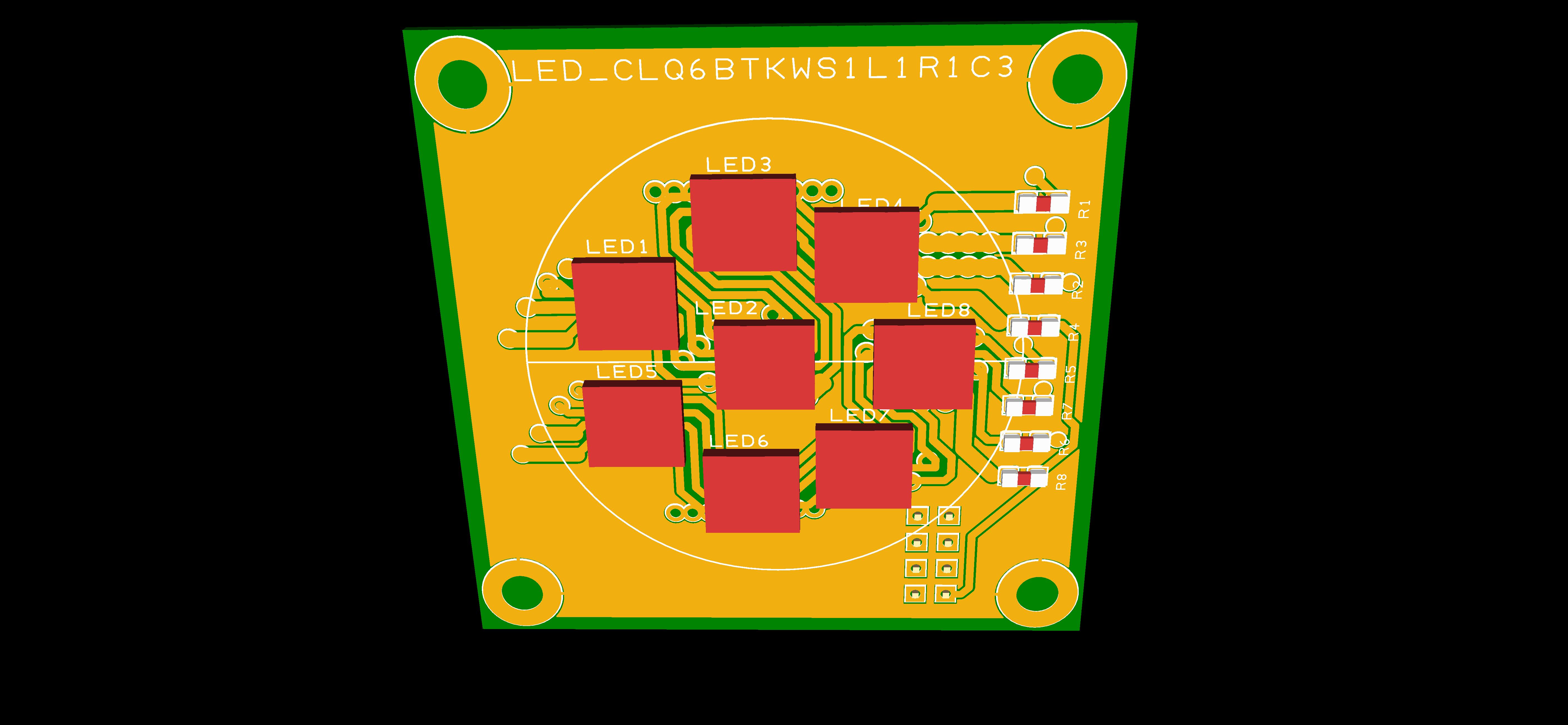
Single or multi colour, in short, a multi-colour device was selected, available from Cree (see data) and Osram (see data) . These contain four light sources - red, green, blue and white. These are designed for use in lighting, are five to ten times (depending how you measure it) brighter than our previous choices, and a board was designed to contain eight such devices. One potential problem, and the reason for our unsatisfactory first choice, whereas they could be soldered by human using a decent soldering iron, these newer devices are 'surface mount' with the connecting pads hidden underneath - you can't get an iron in there! Fortunately we have found an electronics company in Somerset capable of doing this.
A two inch square board with LEDs mounted is part of the job. Each LED will need to be supplied with a reasonably well regulated current to produce the light output we want, and these need to be switched from the signalling control system. Series resistors could be used, but we need to allow for power supply fluctuations, without affecting the brightness or operation of the signal.
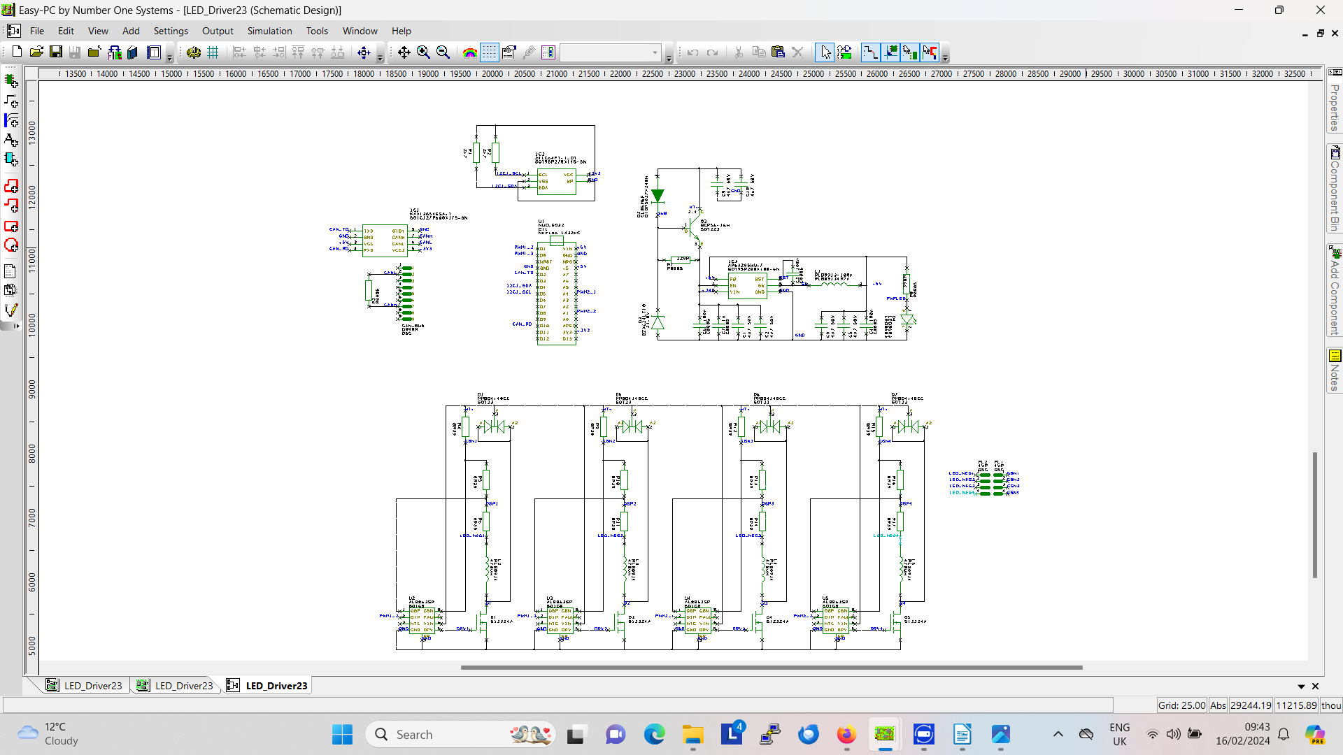
The eight LEDs are connected as a pair of series connected sets of four, in parallel. The small resistors shown ensure currents in each set are substantialy the same. This configuration should work well with supply voltage of 12V or above.
Interrogating industrial component suppliers, a search was made for 'LED drivers', and an eminently suitable low cost (£0.65), variable brightness driver was found, AL8863SP.
With few extra components, four of these can accurately control the current to each of the four colours of LED.
Driven by four pulse width modulator controller outputs, the lights are controllable to produce any blend of colours at all possible intensities. This is probably more than strictly needed for our signals, but provides a versatile platform for evaluation.
The 'Multicolour LED Controller' schematic includes a full CAN bus interface.
We have the choice of two methods of wiring all the site connections. We could wire each item individually back to a central signal 'box'. This would mean combining many twisted pairs (or whatever) into a big fat bundle entering the signal box. This is the mid-20th century telephone exchange method.
Alternatively, we can design a CAN bus interface into points, signals and any item of signalling equipment. This requires just one twisted pair, daisy chaining all items where ever they are. One aditional wire pair is required for power.
Clearly, the simplicity of a full CAN bus implimentation is attractive, the down side being greater expense at every node (about £10 or thereabouts).
The final outcome will be a mix-and-match, with, for example, the telephone exchange model used exclusively on the level crossing where cable runs are short, with CAN bus devices at more distant positions.
For lineside railway signals, whether LED or semaphore, the CAN bus interface is preferred as it requires only four electrical connections. A non-CAN bus signal requires six. If signal heads are regularly removed, a robust reasonably weather-proof connector will be needed. In this case four pole is preferred.
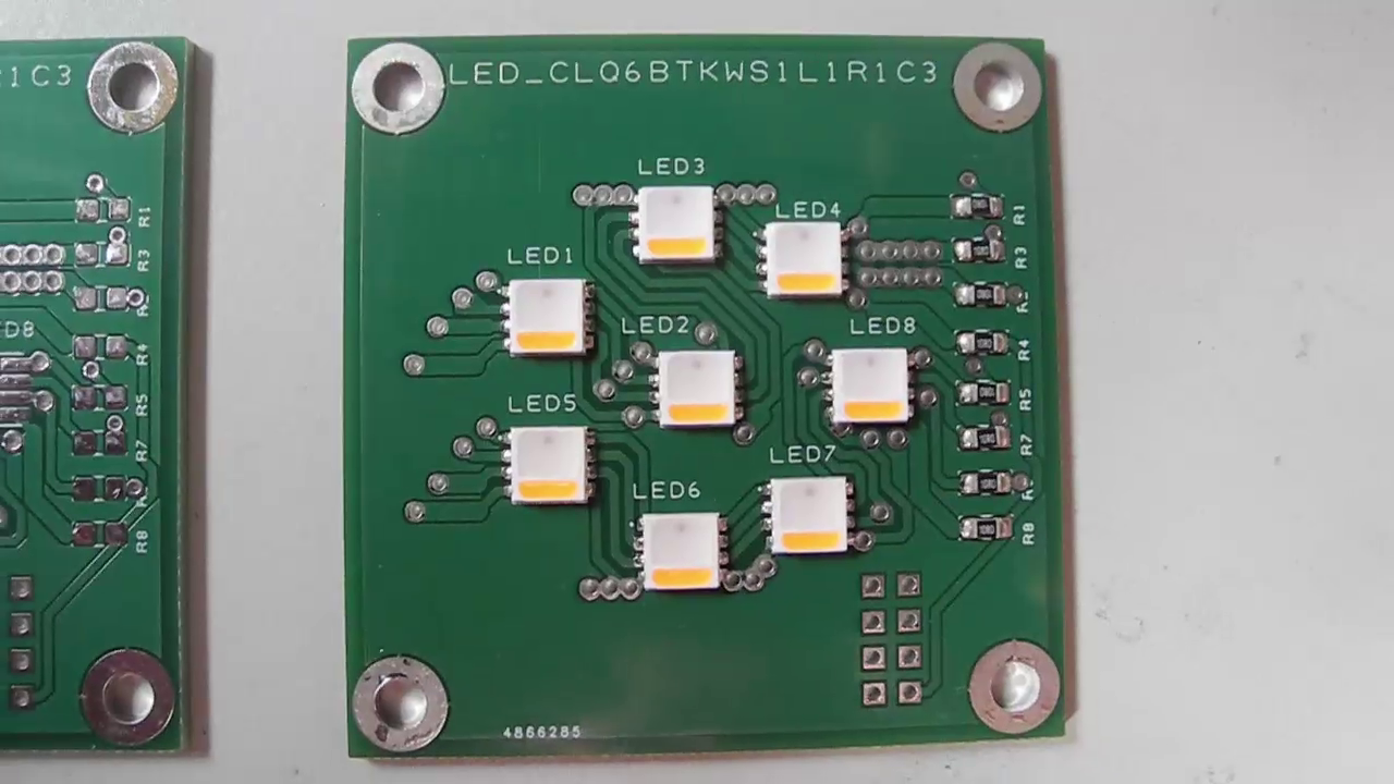
Update March 2024 - Have now procured the PCBs and all components. The prototype signal head consists of two 'piggy-backed' circuit boards, a controller system and the display boards. Controllers were assembled 'in house', but the LED panels use surface mount devices that can not be soldered using traditional hand-soldering. Instead, the job of assembling a batch of 10 was offered to Circuitbase Ltd of Bridgwater. Tiago, the main man there, was most helpful. They did a great job, delivering 10 superbly assembled boards in double-quick time. Excellent service, more work will surely be put their way. Well done!
A prototype circuit board was designed to take a few components including one ‘Nucleo L432KC’, four LED driver circuits, a MAX13054 CAN bus line driver, and a memory chip to store a unique node ID, so that separate signal heads may be individually addressed. Once complete, the PCB design files were emailed to China, and a few days later the bare PCBs arrived. Once built, it took little time before the coloured light system was drivable from the laptop using a USB connection. This proved we could control the brightness of the four colours separately. A ‘brightness’ control was written into the code to allow brightness settings from 0% (off) to 100% (max). For working on the bench the full brightness was too painful to look at, further bench work continued with brightness reduced to just 1% !
As often when working with prototypes, the need for a minor design modification became apparent. During reprogramming or other times when the L432KC was not directly driving the LED drivers, the PWM outputs revert to high impedance allowing the LED drivers to default to maximum brightness. This caused the failure of one LED module as the LED power rating assumes the equivalent maximum of any one LED at max power, or any two at half power, etc. All four at full power together was enough to melt the silicon and let the smoke out. This problem was solved with the addition of four ‘pull-down’ resistors to explicitly switch the LEDs off during these moments.
Half a century ago small resistors might have cost around three pence each. Today, small surface mount resistors may be bought on reels of five thousand parts for around three pounds. They are literally less than ‘ten a penny’. While recklessly ‘splashing the cash’ in this way, it was decided to add another three resistors configured as a potential divider. This would give the controller in the signal box the ability to read the supply voltage reaching any given signal. Useful? Who knows?
For further information, see our video on Facebook
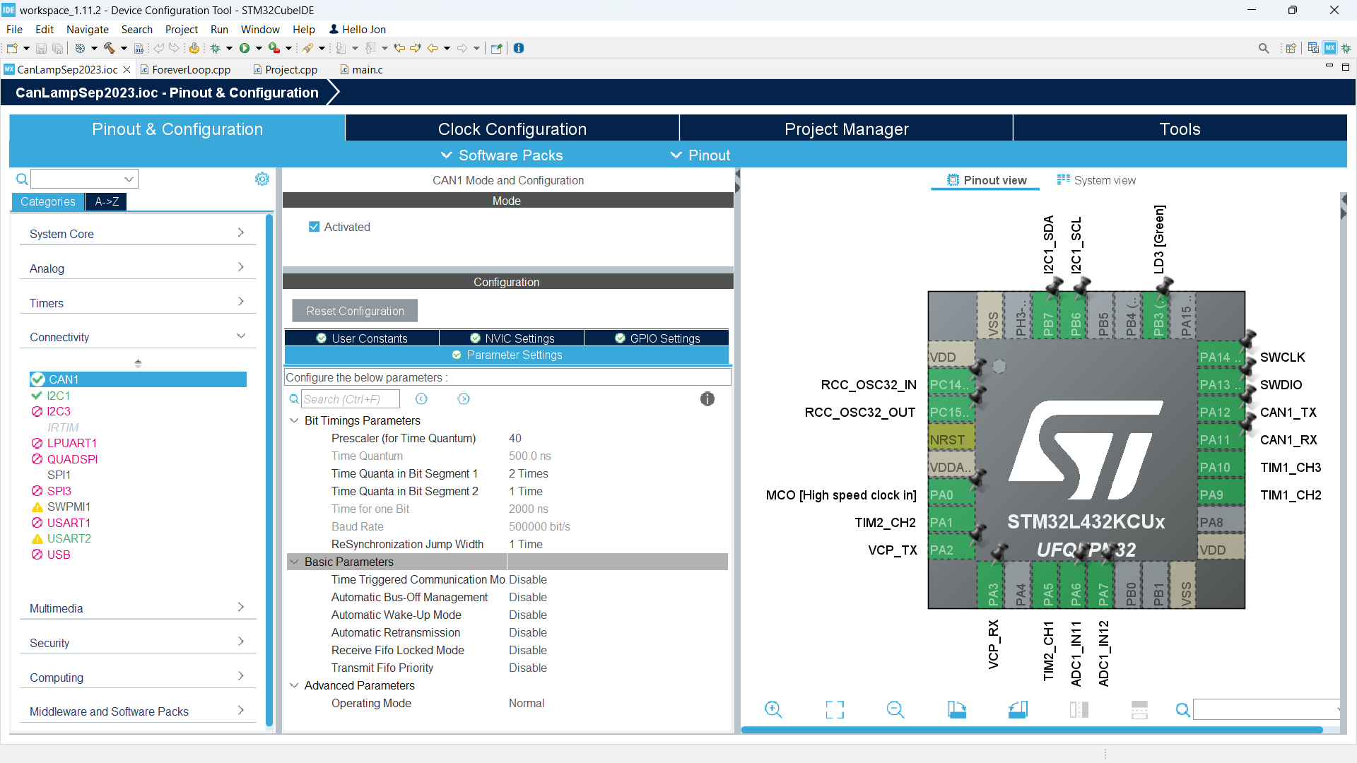
The last part to prove – CAN bus communication. Last year we designed and built prototype signalling system controllers featuring, amongst many other features, a CAN bus port. Having nothing to ‘talk to’, the CAN bus port remained untested. The task remaining was to get a controller ‘talking to’ a signal head, and here we benefit from the high level of integration of the STM32 ‘ARM Cortex’ microcontroller family and the ease of use of the STM32CubeIDE.
At the design stage, the IDE helps in the choice of which chip pins we’re going to use for what purposes. Most pins offer a choice of function but no pin can do everything. The 'Using STM32CubeIDE' figure (left) shows the chip footprint in the IDE. Selecting pins is as simple as clicking on the pin and choosing its function from a list. In the centre pane we see selected the CAN setup data. Here the prescaler and various time variables were fiddled with to get the ‘Baud Rate’ to 500000 bit/s. All the rest were left as defaults. The default option is most often the one we need! Once we’ve been around all the setups for all the L432 features we are using, the IDE will ‘Generate Code’ for us, a file “main.c”, often around 600 lines of code. This is all the ‘startup’ code where all sections of the computer get set up for us. This represents a huge saving in work for us. In earlier times, all of this would have been done by hand – a long, tedious and difficult task! Much of the “main.c” file might seem impenetrable gobbledegook to the uninitiated, but we needn’t be too concerned. Most of it we’ll never need to look at, but simple additions will be made in some of the areas clearly marked for our input.
Having gone around all the IDE options expressing our preferences, and with startup code generated, we can be almost certain all parts of the L432 will perform as we want. For example, the selected timers will be working as pulse width modulators, and there will be no doubt the CAN bus interface is all setup ready for our use. What it doesn’t help us with is how to go about batting messages back and forth over the CAN bus. For that a search of the net found all that was missing. A first class tutorial was found at https://controllerstech.com/can-protocol-in-stm32/
This is based around the STM32CubeIDE, and showed all we needed to know about messages and message filtering. In a short time we had command messages being correctly sent and received between a signalling controller and two LED signal heads. Very little time has been spent studying CAN bus protocols, little time spent reading about how it resolves conflicts, bus arbitration and all the finer technical detail. Interesting as this may be, we don’t need to understand the engine to drive the car, so to speak.
With everything seen to work as expected, a polycarbonate enclosure was sourced into which the prototype almost fits. A revised final PCB will fit perfectly. The enclosure is IP67 rated, meaning it should be sufficiently weather-proof for outdoor installation. Other changes between prototype and production include replacing the Nucleo L432 module with a ‘bare metal’ L432 computer chip variant with 48 pins instead of 32, simply to make the PCB layout easier. This chip will cost around three pounds (half a pint) compared to the tenner for a Nucleo module, but will necessitate use of an external ‘ST-Link’ programmer (for a one-off cost around twenty pounds).
However, this is TME, where the 'lore' is that spanners will get thrown into any work in progress. It has now been decreed lineside LED signals will include two lamps. Pain yes, big problem no, as this news came before the driver board reworking which can be made to accommodate two LED modules. Of course the revised design will not fit the enclosure previously sourced.