Signalling System - Top Level Overview (Update December 2025)
Generic Control System
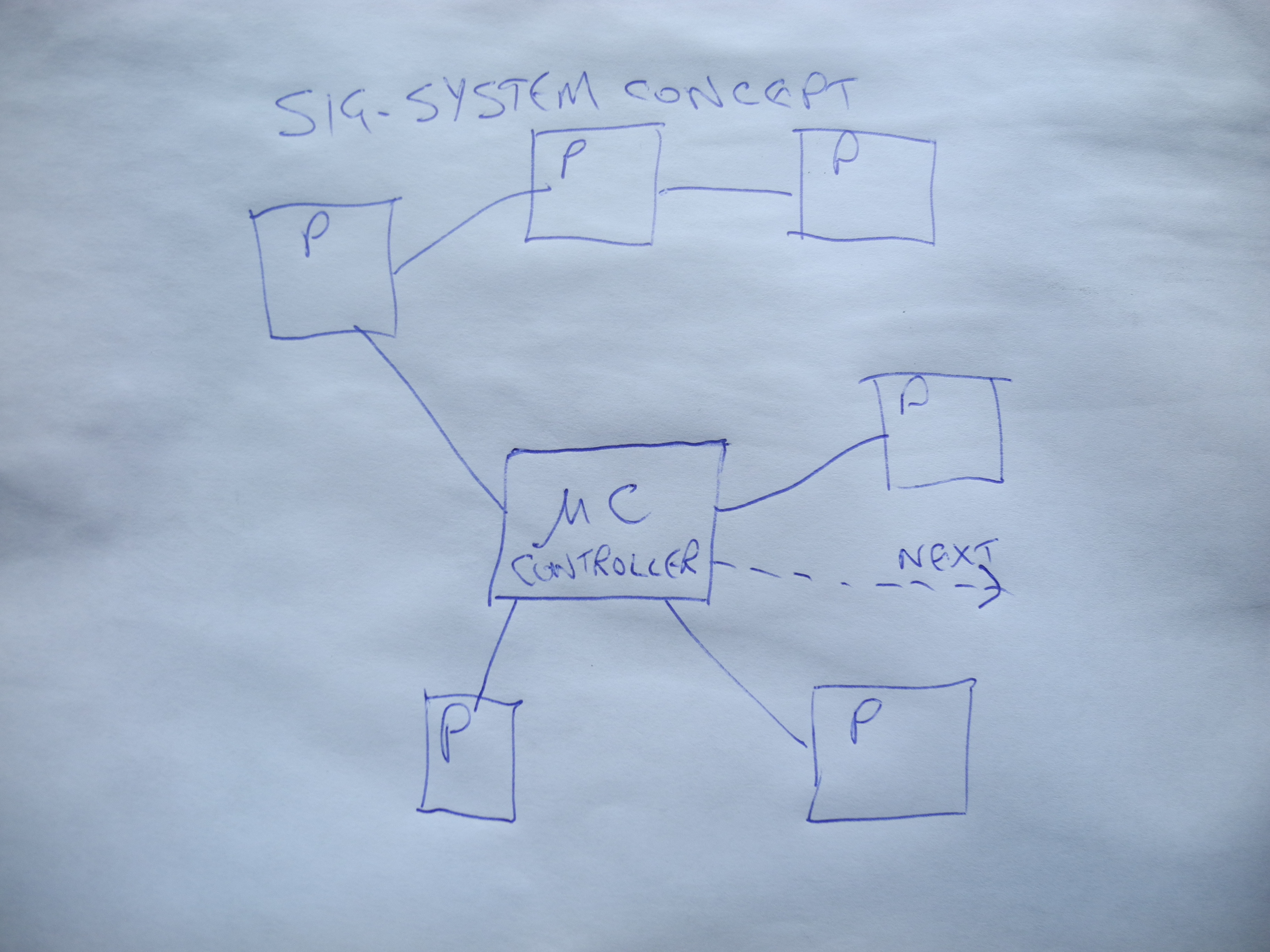
The Signalling System design uses conventional digital control system principles.
The diagram shows 'μC' microcontroller connected to any number of 'P' peripherals.
The term 'Peripherals' refers to all/any parts of the signalling system - coloured light or semaphore signals, axle detectors, motors, actuators, push buttons, level crossing gates and locks, everything.
Interconnection between system components is either by means of 'CAN bus', or hard-wiring back to centralised Input/Output Expansion modules.
The complete signalling system may consist of a number of such sub-systems linked together.
How It Works
Microcontroller μC runs a section of code known as the 'Forever Loop'. It repeats this action at a regular rate, many times per second.
During each 'Forever Loop' iteration μC monitors the state of all peripherals. Should any change be detected a list of coded peripheral definitions and action plans is interrogated to find what actions, if any, are to be taken.
Peripherals are modelled in code in a style known as 'Object Oriented Programming' (OOP). Any number of, for example, coloured light signal code 'objects' may be created, each with a unique set of rules determining its behaviour. These rules get written into code after interested parties have met and thrashed out what exactly are the rules. This is thought of by signalling oldtimers as 'The Interlocking', which refers back to mechanical signal box design in Victorian times.
Changes to 'The Interlocking' of Victorian equipment is a major undertaking. Simple edits of a text file are all that's needed here.
Microcontroller Module - One Suggested Design
Simple Controller Board
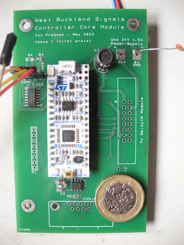
High performance microcontrollers cost almost nothing these days.
For this design a £10 module from ST Microelectronics was chosen. This has more than enough computing power, includes a CAN bus controller, and everything needed, apart from the too few input/output connections. This is addressed by connecting In/Out Expansion module(s) designed for the purpose.
A small circuit board accommodates the microcontroller module with the few extra components needed.
ST Microelectronics provide a free kit of tools for software development, the STM32CubeIDE. This, a laptop and a USB cable complete the development setup. Programming is most easily done using the 'C' and 'C++' programming languages.
NOW DONE - All design and software files are available on GitHub. Take a look by right-clicking here and opening in a new tab.
I/O Expansion Module
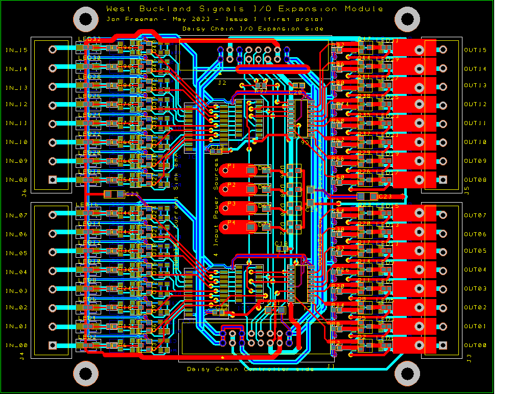
Signalling System In/Out Expansion Module Circuit Board
The screw terminal connections for 16 digital inputs are to the left in the figure (IN_00 - IN_15).
Inputs read the state of switches or sensors in the system. These may be for example push buttons, moving part limit switches etc. A positive voltage (min +5V, max +80V) is applied for an input to be 'Active', an input open circuited or connected to 0V 'Ground' makes input 'Inactive'. The red LED near the input screw terminal lights when 'active'.
The screw terminal connections for 16 digital outputs are to the right in the figure (OUT00 - OUT15).
Outputs may be used to control lights, motors, actuators, alarm bells etc. The blue LED near the output screw terminal lights when 'active'. These outputs are low power, and current limited to 15mA. An 'Inactive' output delivers 0mA and is nominally disconnected. An 'Active' output sources a limited output current of 15mA at a voltage up to +22V.
An output may be used to power one or two inputs. Also four current limited sources are available at P1 to P4. These are for powering inputs or other uses.
An output will in general not be used to directly power signalling equipment, but will be used to drive a local MOSFET switch within the item of equipment. This is in keeping with good practice, keeping high power switching and circuitry localised.
Inputs and outputs have been designed to be rugged, designed to take some quite outrageous abuse without harm.
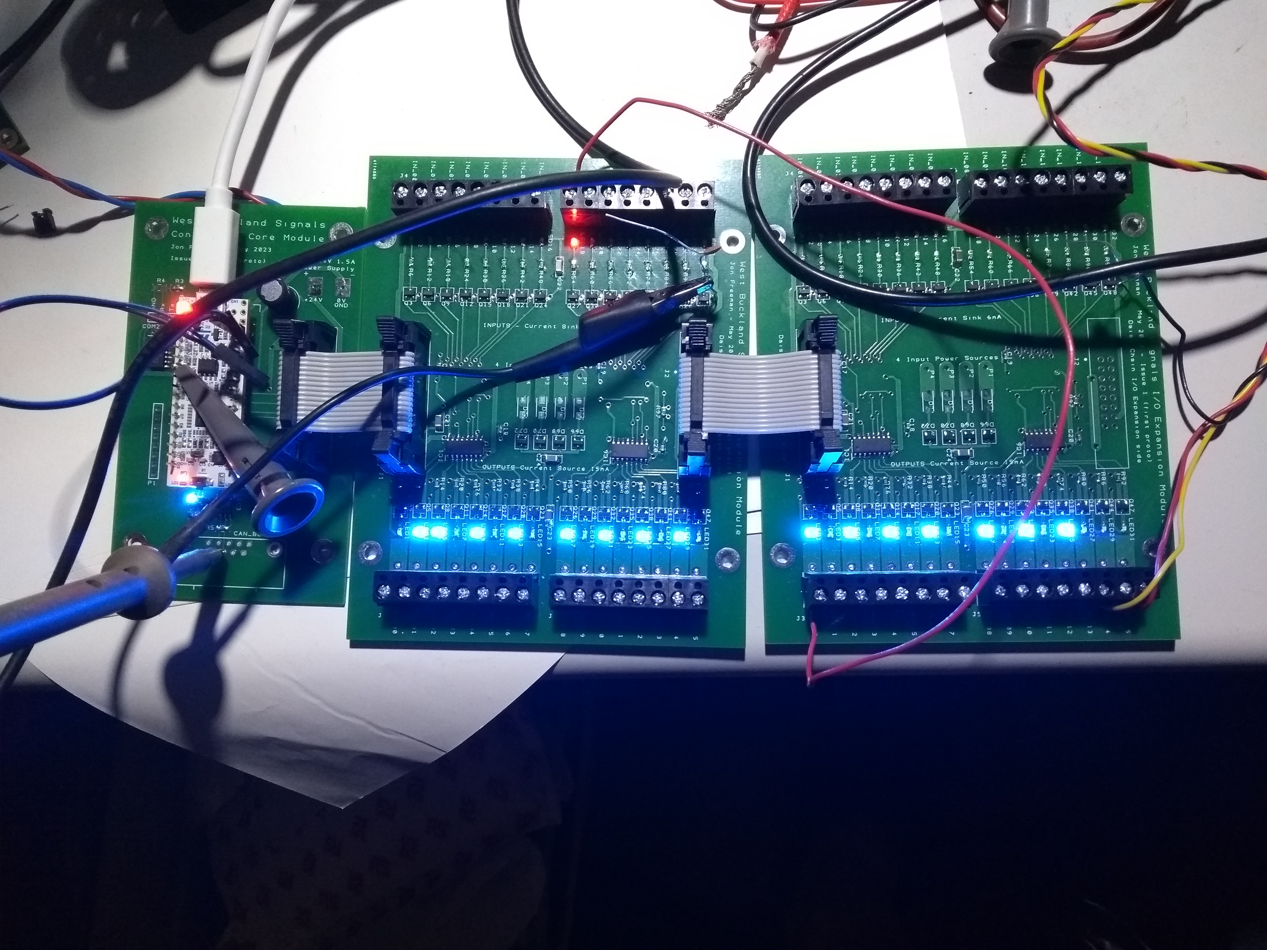
Looking at the 16-pin connectors near the top and bottom in the figure - the bottom connects using a ribbon connector to a microcontroller board - the 'brain' of the system. The upper connector may be used to daisy-chain another In/Out Expansion Module.
See This short video from July 2023 for more on how all this works.
All design files of ANY type, and absolutely everything to do with the signalling system will be found here - eventualy.
Latest Update March 2024. Forever a Work In Progress.