We are not building a Victorian railway.
We are designing and building simple, reliable signalling systems to promote safer running of the railway. 21st century engineering methods and materials are used to ensure objectives are met in a timely and cost effective manner. For lineside railway signals 'coloured light' is the default but semaphore signals may also be used.
At West Buckland we are looking at signalling needs in simple control-system terms, identifying our railway signalling systems as "broad" and "shallow" - that is to say 'broad' encompassing some 'tens of items' to be monitored or controlled, and 'shallow' in the sense that all can be described in terms of simple Boolean expressions evaluating as 'true' or 'false', with no need for analogue processing, mathematics, or anything remotely difficult - No Hidden Depths!
Historic signalling systems may have used complex mechanical arrangements of rods and linkages to implement the logic and safety interlocking. Minor changes involved major rework. Unencumbered by historic baggage, our modern approach builds logic and safety using 'Near Plain English' text files. Rework is easy and cost free.
Use will be made of British designed 'ARM Cortex' controllers, the most widely used controller family worldwide. Several manufacturers offer ARM Cortex variants, our chosen is ST Microelectronics, their "STM32CubeIDE" enables very short design cycles, making best use of the architecture. Wide support ensures these controllers will be workable, and re-workable, for many years to come.
Programming languages are "C" and "C++". These are regulated by ISO - world standards, NOT corporate interests. This ensures code will remain re-workable for the foreseeable future. Improvements are regularly introduced into "C++" (a superset of "C"), better methods have evolved over decades, additions are introduced, but nothing gets taken out. That's how we can be certain our code has a secure future.
Using "C++" we can design the behaviours of our signalling system using statements recognisable as 'Plain English'. Recourse to 'relay ladder logic' or other obsolete terminologies or methods are discouraged as unhelpful and unnecessary distractions.
As designed, at first 'switch-on', all railway signals will show "Danger", and that's the way it'll stay until we have given the signalling system good reason to do otherwise. 'Plain English'-like Boolean expressions for each signal provide the justification for other display aspects.
For example, suppose there is a signal named 'Sig13'. Conditions for this to show "Clear" might be that:-
Putting this in even plainer English, "Sig13 Clear when :
(TurnoutNo7 ahead set for 'Route A' AND Level crossing safe to cross AND No train in section ahead)"
This is very close to the Boolean expression to enter in the code for Sig13. For the expression to evaluate 'true' and so to show a 'Clear' aspect, condition1 AND condition2 AND condition3 must all evaluate 'true'. Any one or more being 'false' will keep the signal set to 'Danger'.
Of course, for the signalling system to work, it will need to be able to read the position of TurnoutNo7, will need to be able to read and verify all four level crossing gates and any gate locks are in the 'safe' position, and to have kept note of train movements to be certain section ahead is clear.
But then, a decision is reached that this is wrong as the Sig13 signal should indicate 'Clear' for either route 'A' or route 'B', and the code is changed to remove the constraint of TurnoutNo7 simplifying the expression to :
(Level crossing safe to cross AND No train in section ahead)
After a number of derailments on TurnoutNo7, it is realised the expression for Sig13 should check that TurnoutNo7 is set safely for one route or the other as for a number of reasons the turnout blades could be positioned to cause derailments. This problem is solved by modifying the expression once again to :
((TurnoutNo7 ahead set for 'Route A' OR TurnoutNo7 ahead set for 'Route B') AND Level crossing safe to cross AND No train in section ahead)
In general, the position of all moving parts of the railway - semaphore signals, gates, turnouts, locks, levers - must be readable by the signalling system, because it can not act upon information it has not got!.
Controllers for 'wide, shallow' systems such as WB signalling can be very simple and low cost.

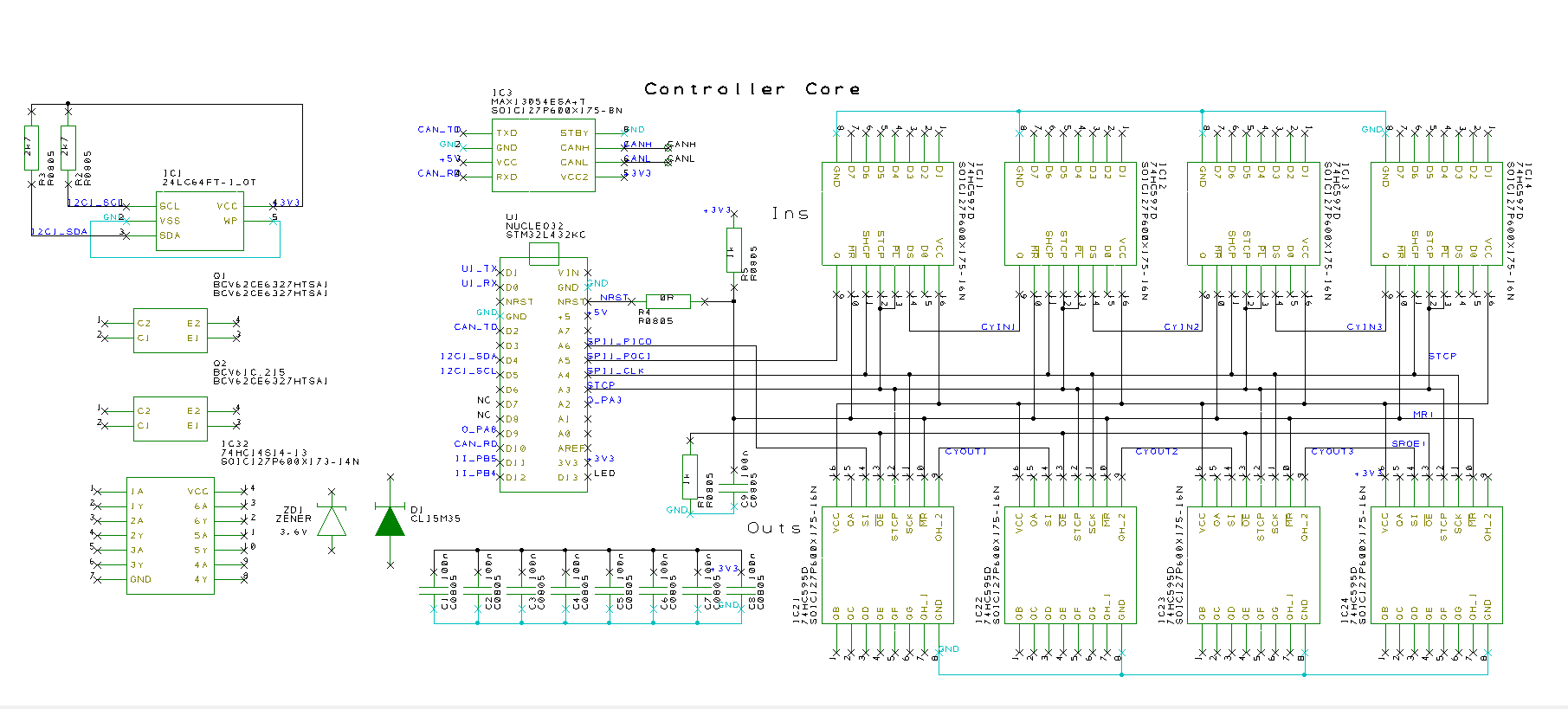
The above shows the essential elements of the control system. The ultimate control element is the low cost STM32L432KC module. Expansion to provide the high number of input/output lines required is achieved by daisy-chaining 74HC595 and 74HC597 shift registers - four stages shown above providing 32 each inputs and outputs. Any practical number of stages may be added.
Other niceties - IC3 is a CAN bus interface for linking a number of controllers (if required). IC1 is a memory for storing local setup or other info.
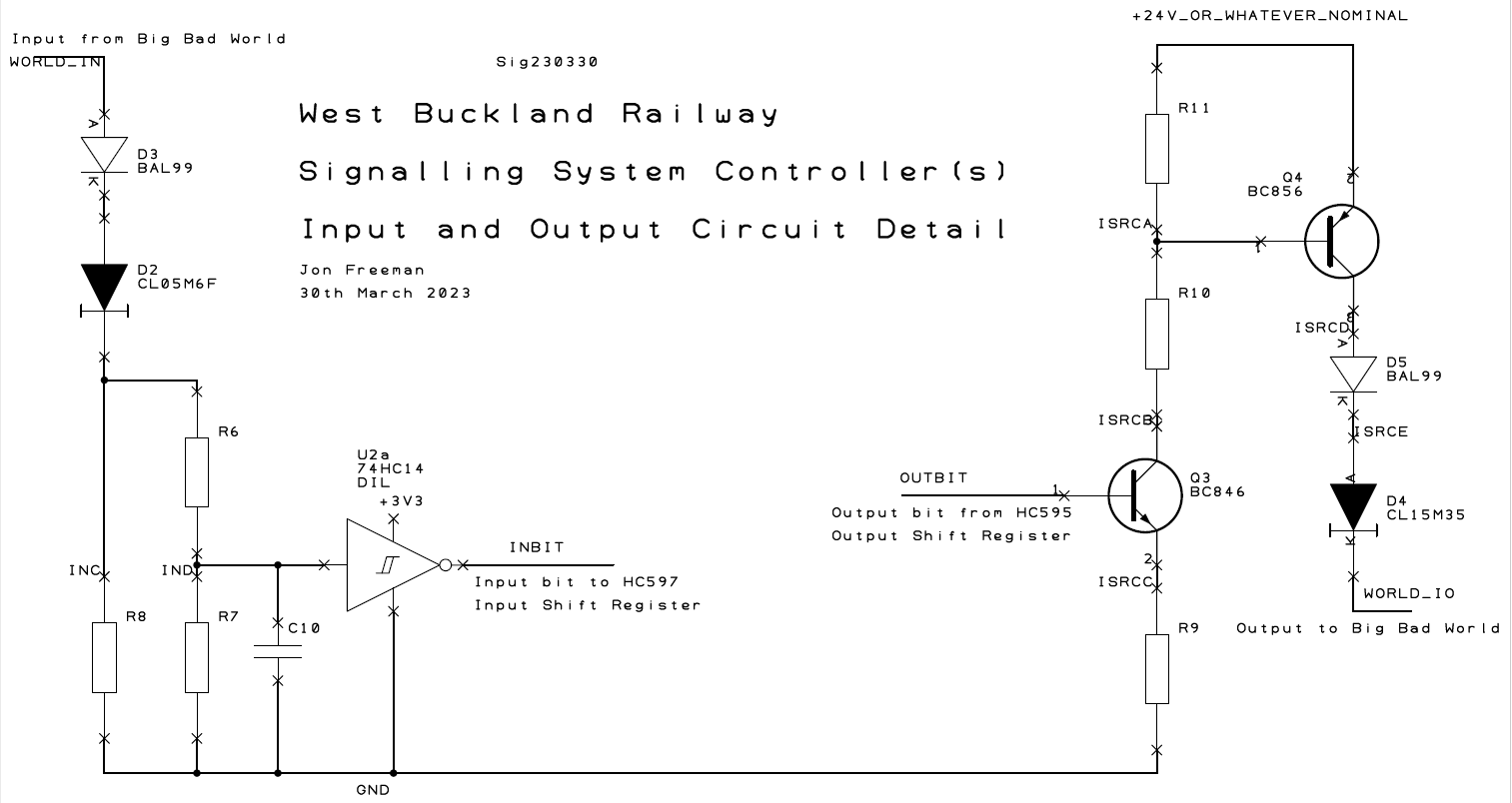
The 'logic level' electrical signals internal to the controller are low voltage, low power. Interfacing to the 'Big Bad World' sensibly requires that the connections seen on the outside of the controller box be, as far as possible, infinitely abusable. That's the task of the IO Interfaces.

Above, left input interface, right output interface.
Input - Inputs are standard 'current sink' design. Positive input currents rising > 4mA will be read by the controller as '1'. Hysteresis provided by the 74HC14 Schmitt trigger ensures noise immunity, positive input currents falling < 2mA will be read as '0'. Protection against abuse of inputs : D3 provides protection against application of negative input voltages to -70V. This will be sufficient in this system with no negative supplies. D2 is a 'constant current diode' (see data) which passes nominal 5.6mA for voltages in range of 3 - 190 volt so providing protection for positive voltages much higher than found in the system. R6, R7, R8 allow for accommodation of future 'ah but' requests. C10 rolls off any high frequency response.
Output - Outputs are standard 'current source' design. Q3, R9, R10 form a switched current sink controlled by a controller output shift register bit. A logic '1' turns on the sink which biases Q4 into a state where it would be capable of sourcing > 100mA. D4 is another constant current diode, limiting output source current to 15mA. D5 protects against damage from high positive voltages applied to output connections.
The overall system may need more inputs than outputs. Allowing for equal numbers results in the likely availability of 'spare' outputs which could be used to power inputs, avoiding the need for separate input power sources - good design practice.
Output current sourcing capability is a little more than twice input current. This ensure one or two inputs powered per output, will be read correctly. Using 'spare' outputs to power inputs makes possible implementation of certain logic funcions through the ability to power or de-power individual inputs. Using 'wired logic' in this manner is however discouraged, as any intention is unlikely to be discernable reading the hand-coded boolean expressions intended to define system behaviour.